Tuesday, July 1, 2008

Keeping It Green: Advances in Textiles for Vacuum Infusion Processing

Wind power’s portrayal as a 100% clean source of renewable energy bodes well for those seeking a power source with little environmental impact. Nevertheless, to stay true to this green promise, we mustn’t lose sight of the carbon footprint laid down prior to the generation of electricity. Composite materials, acknowledged as an enabler of the green promise, can contribute greatly to this footprint. In recognition of this reality, manufacturers’ have turned from open mold processing to closed mold vacuum infusion processing.

Closed-mold vacuum infusion processing of composites, is recognized as offering reduced volatile emissions, higher fiber content, and improved laminate quality relative to the baseline open mold wet lay-up process. Additional benefits include a low capital investment and an easily manageable learning curve. Accordingly, examples of its use in wind turbine construction abound, from rotor blades to nacelles. Recent advances in infusion specific textiles present an evolutionary step towards further reductions in manufacturing costs while reducing the carbon footprint for wind turbine manufacturers. The advantages these products pose extend beyond consideration of cost and carbon footprint, however, as they offer superior post-fabrication adhesive joining of composite structures.

Process Explanation
Vacuum infusion processing was born from the desire to mate the value proposition of aerospace closed molding to the needs of the commercial manufacturer engaged in open mold processing. In closed mold processing, liquid resin is injected using a pressure gradient. In vacuum infusion processing, negative pressure provides the gradient needed to motivate resin flow.

There are two basic vacuum infusion-processing techniques: surface infusion and inter-laminar infusion. In both practices, a flexible bag or membrane is sealed to a rigid mold to form the “closed” mold. As the closed mold is evacuated by vacuum, the bag collapses against the pre-form, consolidating it against the mold. While this consolidation promotes high fiber content in the final laminate, it does so at the expense of in-plane resin flow. Hence both practices employ a distribution medium designed to facilitate in-plane resin flow, allowing out-of-plane (through thickness) resin infusion to occur. The terms surface infusion and inter-laminar infusion denote the location of the distribution medium relative to the laminae pre-form.

In conventional surface infusion (Figure 1), a removable layer, commonly referred to as a peel-ply, is placed on top of the pre-form before applying the flexible bag and the distribution medium and/or perforated injection tubing is placed on top of the peel-ply. Once the bag is in place, vacuum is applied and resin is drawn through feed-lines into the mold across the distribution medium and through the pre-form. Upon resin cure, the bag is removed, as are the peel-ply and distribution medium, which are subsequently disposed. The peel-ply facilitates removal of the distribution medium while leaving a textured surface on the part for improved secondary bonding. To date, the greatest drawback of surface infusion has been the high waste and cost associated with the application, removal, and disposal of peel-plies and distribution media.


Figure 1. General Surface Infusion Illustration

In inter-laminar infusion (Figure 2), the distribution medium is integrated with other laminae in the ply stacking sequence, typically in the center or neutral axis, and maintains an open porosity while the laminae pre-form is being compressed under vacuum. Because the distribution medium remains within the laminate, the need for peel-ply can be reduced to areas where a textured surface is desired. Since the composite becomes the infusion pathway, placement of vacuum and resin feed lines is simplified and the post-process waste stream is reduced. Inter-laminar infusion is particularly proficient at infusing thick composites because its placement in the center of the ply stack halves the out of plane distance the resin needs to travel. To date, the non-structural nature of available distribution media has been cause for concern, even when used in the neutral axis.


Figure 2. General Inter-laminar Infusion Illustration


Advances in textile design have led to the development of a new class of distribution media known as Infusion Flow Reinforcements™ (IFR). Aptly named, this class of textiles facilitates infusion flow while contributing to the laminate as a constituent material. This shift in thinking broadens process control for inter-laminar infusion and affords the opportunity to eliminate the waste stream associated with conventional surface infusion. In inter-laminar infusion, ply stack placement of an IFR wouldn’t necessarily be limited to the neutral axis. Placement of IFR would be driven by optimum flow considerations (i.e. off-neutral axis or in multi layers in a thick composite). In surface infusion, IFR could be used as the last ply in the laminae, replacing the disposable medium, and potentially eliminating the need for peel-ply altogether.

Application Study

Recently, Polynova Composites participated in a test program to evaluate a commercially available IFR, HIFLUX-90™, as the last ply in surface infusion.
Constructed of high tenacity polyester fiber, the open nature of this textile, shown in Figure 3, assures a high degree of out-of-plane permeability, while its periodically raised or ribbed members (knops) lend a third-dimensional prominence to separate adjacent layers and ensure bi-lateral in-plane resin flow. Engineered with preferential in-plane flow in the weft [90°] direction, the product is well suited for high aspect ratio applications, such as wind blades, where the width presents the shortest infusion path. Further, its good hand and drape eases lay-up of complex parts.


Figure 3. Example IFR


The test program investigated the lap shear and cross peel adhesive performance of ITW Plexus® MA530, MA560 and MA590 methyl methacrylate adhesives. The adhesives were used to bond composite substrates: (i) identical peel-ply textured surface coupons; and (ii) identical HIFLUX-90™ surface coupons.

Both composite substrate panels were fabricated at Polynova Composites, of Milford, Massachusetts, USA, by surface infusion using Ashland Aropol 63301-10 INF polyester resin initiated with 2 wt./% Norox CHP. Both resin and room temperature were 23°C, and both composite panels were infused under 91.43 kPa vacuum. Table 1 identifies the substrate laminate schedules.


Table 2 compares the measured lamina and laminate weights and highlights for both panels.


Table 3 presents the measured post-fabrication waste stream associated with the use of the peel-ply, disposable distribution medium, and associated resin.


Tensile lap shear testing was performed in accordance with ASTM D 5868 and cross peel testing was performed in accordance with SAE J1553. For each adhesive, test specimens were created by dry rag wiping the substrates then bonding coupons at room temperature. The bond line was 0.0762 cm in each case.

Study Results
Table 4 contains all lap shear data for this study and Table 5 contains all cross peel data for this study.

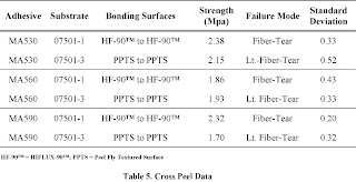


Plexus® MA530, MA560 and MA590 adhesives produced quality bonds to both the peel-ply textured surface and the HIFLUX-90™ IFR surface, with a favorable Fiber-Tear failure mode noted for the HIFLUX-90™ surface.
Figure 4. Light-Fiber-Tear Failure

For the peel-ply textured surface (07501-3), the mode of failure was Light-Fiber-Tear (Figure 4) which occurs when resin and fibers are pulled free from the surface of one coupon while the adhesive bond-line remains intact on the other coupon. Such failures indicate good adhesion between the adhesive and the substrate, and point to substrate integrity as the limiting factor of obtained strength values.

For the HIFLUX-90™ surface, the mode of failure was Fiber-Tear (Figure 5). Fiber-Tear occurs when resin and fibers are pulled free from within the laminate of one coupon, while the adhesive bond-line and laminate remain intact on the other coupon. Such failures indicate good adhesion between the adhesive and the substrate, and point to substrate integrity as the limiting factor of obtained strength values; examination of the specimens’ reveal that the failure occurred within the E-2LTI 3600 laminae. Also there appears to be a strong correlation between the adhesive gel time and the depth of fiber tear, with longer gel times corresponding to greater depth. This observation holds true for both the lap shear and cross peel sample. This may be attributed to the resin rich surface provided by the HIFLUX-90™ and the extent to which the adhesive is allowed to etch into this surface as a function of time.

Conclusion

Social sentiment has undeniably shifted toward an emphasis on reducing industry’s environmental impact. Governmental policies increasingly reflect such interests. Composite materials are widely recognized as key enablers of the green promise. Ultimately, the wind energy industry must adopt composite processing techniques that truly fulfill the green promise by minimizing the carbon footprint created prior to generation of the first watt. Using Infusion Flow Reinforcements™ as the last ply in a surface infusion process enables the elimination of disposable waste streams, while enhancing post-fabrication adhesive joining of the composite structures in the intended application. These attributes pose a winning combination for the environment and manufacturers of wind turbines. While the Plexus® adhesives present a strong choice for adhering the two composite substrates in this study, it is recommended that customers prepare a testing protocol to determine the adhesives’ suitability for their particular applications and processes.


Lamina Legend:

E-BXM 1708 (Vectorply Corporation)
Fiber Type: E-Glass
Architecture: +45°/-45° Double Bias w/chopped strand mat
45°: 304 g/m2
-45°: 304 g/m2
Chopped Mat: 275 g/m2

E-2LTI 3600 (Vectorply Corporation)
Fiber Type: E-Glass
Architecture: 0°/90°/0°/90° Biaxial
0°: 627 g/m2
90°: 608 g/m2

HIFLUX-90™ (Polynova Composites)
Fiber Type: High Tenacity PET Fiber
Architecture: Proprietary
Areal Weight: 363 g/m2
Knop: Surface projection.
Knop down: projection facing tool surface

Econo Ply E (Airtech International):
Peel ply designed for use in more difficult environments or when a more textured surface is required for secondary bonding.

Resin Flow 75 (Airtech International):
High flow rate disposable surface infusion media

Affiliation:

Patrick Mack is Polynova Composites’ Chief Technologist.

Polynova Composites
229 East Main Street, Ste. 204
Milford, MA 01757 USA

Phone: 508-634-8181
Fax: 508-634-2922

pmack@polynovacomposites.com

http://www.polynovacomposites.com/

Monday, June 30, 2008

Volitalization and the vacuum infusion process revisited

Many users of MEKP are reluctant to reduce vacuum pressure to relieve issues associated with volitalization. A reduction in pressure usually means a heavier part which is unacceptable to some. Keep in mind these "lighter parts" may be dry parts. If there is air in your laminate it will be lighter but significantly weaker.

Thursday, June 12, 2008

Sandwich Construction and the Infusion Process

Despite their many advantages in applications ranging from wind energy to yacht construction to civil and aerospace, fiber reinforced plastic (FRP) laminates are commonly inferior to low-density materials, such as wood, when considering a part’s ability to resist bending moments. For example, since the stiffness of a panel is dependent not only on the material’s flexural modulus, but also on the thickness of the panel, one approach for stiffening an FRP panel would simply be to make it thicker. However, this approach will yield a further increase in weight and potentially unnecessary strength characteristics, construction difficulties, and prohibitive costs in consideration of the final desired structure.

A preferred technique to increase the stiffness of an FRP panel is the use of a sandwich construction. Sandwich construction in a laminate offers the comparable advantages of an I-beam configuration, but instead of the web and flanges of a typical I-beam, sandwich construction makes use of a lightweight core material placed between layers of reinforcement, commonly referred to as skins. The role of the skins in the composite structure is to withstand the bending moments on the panel or beam by resisting the compressive and tensile loading set up in the opposite skins when the panel is subjected to bending load forces.


In order to resist the bending moments, the skins must be rigidly held in a predetermined position relative to the neutral axis of the sandwich (the centerline) and be prevented from moving relative to each other. It is the task of the selected core material and of the strength of the bond line between the skins and the core to provide and meet these requirements. For a given application, irrespective of the selected skin and core materials, the integrity of a sandwich construction is especially dependent upon the interfacial bond strength between the skins and the core elements.

The use of three-dimensional spacer fabrics designed for vacuum infusion, such Polynova Composites Polybeam® Infusion Flow Reinforcement™ (IFR™), provides an opportunity to maximize the skin to core bond while maintaining the physical integrity of the core. IFR™ identifies a class of textiles that both facilitate infusion flow and contribute to the laminate as a constituent material. The Polybeam® family of spacer fabrics applies the wide design latitude of this textile family to solving the needs of the composite marketplace as an IFR™.

Figure 1. Spacer Fabric Architecture.
Three-dimensional spacer fabrics are a class of textiles comprised of two parallel “X/Y” planes of fiber fascia that are separated to a consistent “free form” thickness by columns of Z-directional fibers. Figure 1 schematically illustrates the three-dimensional spacer fabric in a free or relaxed form.


Figure 2. Vacuum Collapsed Spacer Fabric.
As shown in this illustration, a pair of outer, generally woven or knit fabric layers, (1, 2), lying generally in the respective X - Y planes are separated by a plurality of fibers (3) lying generally in a “Z” direction. The overall thickness dimension (d) of the fabric may most usefully be between about 1 or 2 mm up to about 25 or 30 mm, and in some cases even thicker. Frequently, the fiber density for the “Z” fibers may be only a minor fraction of the fiber density of the outer layers (1, 2), but this may also vary according to the architecture and fiber population of the outer layers. The outer layers may range from an open honeycomb structure to a more tightly woven or knit structure.


The IFR™ spacer fabrics for infusion are generally designed to collapse under vacuum pressure, as illustrated in Figure 2, where d is reduced to d’. However, even though collapsed, they are designed such that there remains sufficient mean free path within the collapsed cross-section to facilitate the rapid distribution of resin throughout the structure, including the surrounding and adjacent plies of the entire laminae. The spacer fabric is in the collapsed state at the end of the infusion process and remains collapsed in the final part.

Figure 3. “Spring-back” Enhances Interfacial Planarity.
When a spacer fabric IFR™ having a tightly woven or knit X,Y fascia and resilient Z-direction fibers is used as a lamina between the skin and the core, the resilient nature of the Z-fibers enables “spring back” that enhances the interfacial planarity of the bond line between the core and adjacent laminae, as illustrated in Figure 3.


By way of example, Liquid Access of Melbourne, Florida, USA, a leader in adaptive water ski design, manufacturing, and instruction, turned to Polybeam® IFR™ enabled sandwich construction in order to meet the demands of a unique water ski in a cost effective manner.

Developed in collaboration with World and National Disabled Water Ski Champion, Ann O’Brine-Satterfield, the company’s Sit-Skis enable men and women with a variety of disabilities to pursue the full sport of water skiing from beginner through jump and competition slalom. To date, several hundred skis have been produced and successfully fielded using this technology.

Figure 4. Sit-Ski Laminate Schedule.
In manufacturing the Sit-Skis, the gel coat is first sprayed into a standard female mold with a two-inch flange. As shown in Figure 4, unidirectional carbon fiber is laid into the mold, followed by the Polybeam® IFR™. A plain sheet of ½” foam core precut to fit the mold is then laid in, followed by another ply of the Polybeam® IFR™. Next, the biaxial fiberglass lamina and a semi rigid gel coated floating counter tool (float tool) are placed over the ply stack. The term “floating” refers to the free position of the counter tool within the vacuum envelope. The IFR™ extends beyond the float tool to accommodate the resin feed and vacuum port lines. The resin feed and vacuum ports are then appropriately placed and the infusion proceeds. The ski is released at the end of the cycle and trimmed for delivery. [1]


Enveloping the core with the spacer fabric lends numerous benefits to the sandwich composite beyond enabling the infusion process. The use of the spacer fabric between the core and adjacent lamina enhances the bond strength at this critical interface by rendering the two surfaces planar while accommodating interfacial inconsistencies and allowing efficient energy transfer through the Z fibers.

Figure 5. Infused Double Cut Core Shear Knock Down
The spacer fabric also assures resin flow on both sides of the laminae. A key benefit derived from the use of the spacer fabric IFR™ in this application is that it allows the use of a plain core over an infusion (grooved, perforated, scored) core. This not only eliminates the weight gain and cost associated with an infusion core, but also assures the core properties are maintained. Derived from a recent study using Airex C70.75 core and Ashland AME6000 INF vinyl ester resin, Figure 5 graphically depicts the specific density shear strength knockdown realized when using resin infused double cut core versus a plain core of like density. Here we can see that plain core and post infused double cut core of equal “pre infused density” yield comparable shear properties; however, the resin more than doubles the density of the double cut core. When comparing similar density cores, the plain version will have superior shear properties.


As a further consideration, the grooves, perforations, and scores of an infusion core are filled with a media (resin) having remarkably different mechanical and strength characteristics from either the skin or the core, resulting in a region of divergent stress characteristics – a concern for Liquid Access due to the fatigue and impact loading of the application.

The experience with Liquid Access may have implications in other applications, such as in the design of large wind turbine blades. Research conducted at the Technical University of Denmark by Christian Berggreen, et. al. [2] suggests that as wind turbine blades continue to grow in size, the application of sandwich construction over traditional single skin composites in the flanges of the load carrying spar has the potential to offer weight reductions upwards of 22% with increased buckling capacity. Although this evolutionary step in design shows great potential, the study assumes perfect bonding of the laminae and further indicates sensitivity to imperfections. The use of a spacer fabric IFR™ at the skin to core interface provides a viable strategy for assuring bond integrity at the critical interface, while eliminating the inherent imperfections of the infusion core.

References:

[1] Mack, P., Grisevich, G., “Sit-Skis Get a Makeover”, Composites Manufacturing, 50-53, June 2007

[2] Berggreen, C., Branner, K., Jensen, J. F. and Schultz, J. P., “Application and Analysis of Load Carrying Sandwich Elements in Large Wind Turbine Blades”, Journal of Sandwich Structures and Materials, 9(6):525-552, 2007

Monday, March 10, 2008

Volitalization and the vacuum infusion process

If you've produced a part with vacuum infusion at some point you've probably noticed what appears to be air bubbles in the finished composite. Most likely, what you've seen isn't simply air from the surrounding atmosphere due to a leak in the bag...it's vaporized resin! Understanding the relationship between resin selection, ambient temperature, and vacuum pressure is critical to producing a properly cured part via vacuum infusion.


Recently, Polynova Composites participated in the evaluation of two polyester infusion resins. The test plans called for the production and testing of prototypical solid laminate test coupons wherein the resin system was the only variant. While the resin chemistries were thought to be similar, remarkably one system volatilized to the point of boiling at 24” Hg gauge vacuum (“HgV), whereas the other did so at 27” HgV at room temperature. Since boiling of the resin would result in an unacceptable void content in the final part, and since vacuum pressure plays a critical roll in the infusion process, an investigation was launched to better understand the factors involved.

We turned our attention to improving our understanding of the boiling behavior in the context of known characteristics of the resin systems. Thermodynamically, the boiling point of a liquid can be thought of as the disruption of equilibrium between thermal saturation and corresponding pressure saturation where an increase in thermal energy or a decrease in pressure results in a phase change to the vapor state.

We can visualize the phase change as a function of pressure and temperature with the aid of a phase diagram. Figure 1 is a portion of a hypothetical phase diagram, wherein the phase line separates the liquid and vapor phases. The phases are in equilibrium and co-exist with each other at any point on the line. Phase transitions occur at constant temperature and pressure at


the points on this line. If the pre
ssure is reduced at a given temperature, in this example from p to p’, the phase transition occurs and the liquid boils. Like-wise, an increase in temperature for a given pressure would result in a similar phase transition.


If a single point along the phase line for a given liquid is known, such as the absolute boiling point (a.k.a. the boiling point temperature at atmospheric pressure) the curve can be reasonably extrapolated using thermodynamic equations.

Turning now to the resin system evaluation, plugging the potential bad actor compounds that might cause the resin to boil into the proper thermodynamic equations paints an interesting phase co-existence picture.


While we don’t know the specifics of each resin’s backbone, both were believed to be based on isophathalic acid, and both systems
contain a fair amount of styrene (~35%). The resin systems differ in the type of initiator specified by the manufacturer, where one specifies methyl ethyl ketone peroxide (MEKP) as the free radical initiator, and the other specifies a 60/40 blend of cumene hydroperoxide (CHP) and MEKP as the free radical initiator. The system that volatilized at the higher pressure (~24” HgV) specified the MEKP, whereas the system with the lower volatilization pressure (~27” HgV) specified the CHP/MEKP blend.

The standard boiling point of styrene is 293 F. MEKP’s boiling point and decomposition point are the same at 154.4 F. The standard boiling point of CHP may be derived from the literature boiling point of 213.8 F at 8 mm HgV as being ~503 F. Phase co-existence lines for each compound are plotted in Figure 2.


The boiling point pressures at 77 F are of particular interest, where MEKP boils at 23.184” HgV and styrene and CHP boil at 29.451” HgV and 29.916” HgV, respectively. One can fairly conclude from the plots that the use of MEKP significantly influences the onset of boiling.

When we take a closer look at the pressures/temperatures of interest for vacuum infusion processing, as shown in Figure 3, the affect becomes more apparent as the boiling pressure increases to 20” HgV at 95 F, a temperature that is well within the range of exothermic onset for many resin systems. The implication here is that while volatilization may not be visibly evident during the infusion, it will likely become prevalent just prior to resin gel.


Just how much gas could be evolved? Reviewing the Material Safety Data Sheet for the subject MEKP solution reveals that the actual weight percent methyl ethyl ketone peroxide in the solution is 34%, the rest of the solution being high boiling point components. If we assume a standard 1.5 weight percent addition of the MEKP solution to the resin, our actual MEKP content is 0.51 weight percent. For a 1,000-gram mass of resin, we’re adding 5.1 grams of MEKP. The formula weight of MEKP is ~210, so the mole fraction of the 5.1 grams MEKP added to the 1,000 grams of resin is ~ 0.0242. Using this and the 77 F boiling point pressure for MEKP from Figure 2 (23.184” HgV (gauge)) the ideal gas laws yields a potential of ~ 2.63 liters (160 in3) of evolved gas.

So, does this mean MEKP cannot be used in the infusion process? No. Just how prevalent the evolution of gas is in any given system depends on a number of factors ranging from the resin chemistry and, like the glycol mix in your car’s radiator, its affect on the boiling point of the MEKP, to free radical species evolution and cross-linking during the reaction. Another factor is the selected laminae and its ability to nucleate bubble formation, like Mentos to diet Pepsi. The point, however, remains the same: it doesn’t take very much of a low boiling compound to create a huge void content problem.

A word of caution, while we moved to “pure” CHP as the initiator of choice for the application of interest, as the peroxide plays a critical role in the formation of the thermoset and ultimately it’s physical and mechanical properties, the decision to move to CHP was made under the guidance of the resin manufacturer. Therefore, as you’re thinking about designing and producing your next part, although you’ll clearly benefit from details of this article, don’t be afraid to seek out the wealth of knowledge available from your supply chain.


References for further reading:

1.) W.R. Salzman Website, www.chem.arizona.edu/~salzmanr/, Department of Chemistry, University of Arizona

2.) Modified Trouton’s Rule for Predicting the Entropy of Boiling, Ind. Eng. Chem. Res. (1996), 35, 1788-1792

3.) Some calculations for organic chemists: boiling point variation, Boltzmann factors and the Eyring equation, Tetrahedron Letters 41 (2000) 9879-9882

4.) Ulicky, G., Kemp, T.J., Comprehensive Dictionary of Physical Chemistry, Ellis Horwood Limited (1992)


What is Vacuum?

Atmospheric pressure, the force per unit area exerted against a surface by the weight of the air molecules above that surface, can be measured and expressed in a number of ways. At sea level the standard pressure is 14.7 psia or 29.92" of mercury (Hg) or 760 mm of mercury (Torr). Because the atmospheric pressure varies with weather and altitude, the sea level pressures are used as a reference point. The term "vacuum" describes pressure that is below atmospheric pressure.

nches of mercury ("Hg) are a common measure of vacuum and are expressed in two different ways. One way is in "Hg gauge ("HgV), where the scale starts at 0"Hg (atmospheric pressure) and goes to 29.92" Hg, or full vacuum. The other way is in "Hg absolute ("HgA), where the scale is reversed such that the gauge reads 29.92" Hg at atmospheric pressure and 0" Hg at full vacuum. To relate the two methods 24" Hg gauge pressure at sea level would be 29.92 - 24 = 5.92"Hg absolute pressure.

Polybeam enabled cabin top infusion

On February 5th 2008 the Landing School of Boat Building and Design infused a cabin top for a small powerboat. Polybeam703 was utilized as an infusion flow reinforcement to allow rapid and uniform resin flow. Polybeam703 was layed directly against the plain balsa core to act as both a structural reinforcement and flow media. The z axis fibers improve damage tolerance and shear strength, while the smooth surface profile allows for excellent bond strength between the core and skins.

The laminate schedule consisted of the following materials and resin.

Vectorply E-LTM 1808
Polynova Polybeam703
1/2" Balsa
Polynova Polybeam703
Vectorply E-LTM 1808

Resin: Pro-Set epoxy 500-700 cps viscosity

Seven resin feeds were setup using Enkafusion strips as the resin carrier. Rope was used to facilitate the vacuum around the perimeter of the tool. The total infusion time was approximately 30 minutes.


Part prior to infusion


Finished part